Generic DAQ Devices
Any device that simply requires direct access to one or more DAQ channels may be configured as a ‘DAQGeneric’ device. For example, this includes:
Analog detector devices such as photodiodes, laser power meters, temperature probes, and electrode amplifiers.
TTL-driven devices such as shutters and solenoid valves.
Analog output devices such as LEDs and stimulating electrodes.
DAQGeneric devices may be operated using the TaskRunner module to perform a wide variety of recording and output tasks. Devices that require access to DAQ channels with more advanced or device-specific features are implemented separately (for example, patch clamp amplifiers, galvanometric scan mirrors, lasers, and cameras), but usually inherit much of their behavior from the DAQGeneric device class.
Configuration Options
The basic DAQGeneric device configuration includes one or more channel specifications:
Channel specification
Many device types in ACQ4, including DAQGeneric devices, declare connections to DAQ channels using the same specification format:
ChannelName:
    device: '<DAQ_Name>'
    channel: '</DevN/channelName>'
    type: 'ai' | 'ao' | 'di' | 'do'
    mode: 'rse' | 'nrse' | 'diff'
    holding: <output value>
    units: '<unit string>'
    scale: <scale value>
    offset: <offset value>
    settlingTime: <time value>
    measurementTime: <time value>
The required parameters for each channel are:
ChannelName: A user-readable name indicating the purpose of this channel. For DAQGeneric devices, this name may be chosen by the user. All other device types expect to have specific channel names configured.
device: The name of the DAQ device where this channel is found.
channel: A string indicating which channel on device the connection is to. For NiDAQ devices, these usually look like ‘/Dev1/ai0’ for analog inputs, ‘/Dev1/ao0’ for analog outputs, or ‘/Dev1/line0’ for digital i/o lines. Note that the name ‘Dev1’ is configured by the Ni DAQmx system, and may differ across machines. See the National Instruments documentation for more information.
type: One of ‘ai’, ‘ao’, ‘di’, ‘do’ indicating the intended use of the device.
Optional parameters are:
mode: Specifies the recording mode for analog input channels; one of ‘rse’, ‘nrse’, or ‘diff’. If unspecified, the default value from the DAQ configuration **defaultAIMode** option will be used. See the National Instruments documentation for more information.
holding: The default output value for this channel (not used for input channels). When the channel is not being used in a Task, its output is set to the current holding value. This value may include a unit specification.
units: A string indicating the units to use when describing the input or output values for this channel. Units should always omit the SI scaling prefix. For example always use ‘V’ instead of ‘mV’; the scaling is described in a separate parameter.
scale: Scale factor for this channel. For clarity, it is recommended to include a unit specification. Voltages recorded from input channels are multiplied by this scale factor to convert to the appropriate units. Likewise, output values given in the appropriate physical units are multiplied by this value to convert to voltage.
offset: Offset value to be added to input data or output voltage.
settlingTime: This rarely-used option is used with input channels to aid in automatic Task construction. It indicates the amount of time to wait before a change in the state of the device will be accurately reflected in the channel voltage.
measurementTime: This rarely-used option is used with input channels to aid in automatic Task construction. It indicates the recommended amount of time to record from the channel in order to achieve an accurate measurement (assuming the entire recording will be averaged together).
Examples
Example configuration for controlling a laser Q-switch and shutter via two digital output lines:
LaserControl:
    driver: 'DAQGeneric'
    channels:
        shutter:
            device: 'DAQ'
            channel: '/Dev1/line30'
            type: 'do'
            holding: 0
        qSwitch:
            device: 'DAQ'
            channel: '/Dev1/line29'
            type: 'do'
            holding: 0
Example AxoProbe 1A configuration:
AxoProbe1A:
    driver: 'DAQGeneric'
    channels:
        Command:
            device: 'DAQ'
            channel: '/Dev1/ao0'
            type: 'ao'
            units: u'A'
            scale: (1*V)/(2*nA) ## scale is for headstage H = 0.1L, I = 20H nA/V = 2nA/V : 1V/2nA
            userScale: 1*pA  ## tells scale for output to be in units of pA
        ScaledSignalV:
            device: 'DAQ'
            channel: '/Dev1/ai3'
            type: 'ai'
            units: u'V'
            scale: 10 ## net gain is fixed at 10 (if f1 switch is set to 10V1): 1V/0.1V
        ScaledSignalI:
            device: 'DAQ'
            channel: '/Dev1/ai4'
            type: 'ai'
            units: u'A'
            scale: (1*V)/(10*nA) ## scale is H = 0.1, gain = 10/H mV/nA = 100 mV/nA: 1V/10nA
Example configuration for a calibrated photodiode:
Photodiode-UV:
    driver: 'DAQGeneric'
    channels:
        Photodiode:
            device: 'DAQ'
            channel: '/Dev1/ai7'
            type: 'ai'
            scale: 49.1*mW/V  ## calibrated 2011.11.09
            offset: 0.0*mV
            units: 'W'
            settlingTime: 2*ms
            measurementTime: 50*ms
Manager Interface
The Manager user interface for DAQGeneric devices will contain one control panel for each channel defined on the device.
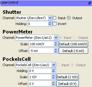
Output channels have a Holding value that indicates the default value of that output when it is not being used in a task. Analog channels display Scale and Offset parameters as well. By default, each of these is loaded with the value given in the configuration file for the device. Modifying these values will change the behavior of the device while ACQ4 is running, but will not modify the original configuration file. Clicking any of the Default buttons will reset that parameter to the value that is defined in the configuration file.
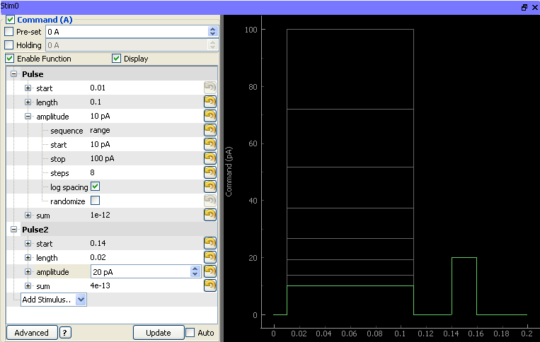
Task Runner Interface
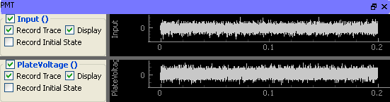
The Task Runner interface for DAQGeneric devices includes one plot area for each channel That displays either the recorded signal or the generated output waveform for that channel. A Display check box controls whether the plot area is visible.
Input channels also have a Record option which allows recording from the channel to be temporarily disabled, and a Record initial state option which causes the input value of the channel to be recorded once before the task and stored as metadata on the task results directory. This is used, for example, to make measurements from temperature probes where it is not necessary to acquire a complete waveform.
Output channels have a function generator that is used to define the output waveform and sequence parameters. Also included are a Pre-set option, which sets the output value on the channel immediately before starting the task, and a Holding option, which (if checked) will alter the holding value for the channel after the task has completed. Note that, whether or not Holding is checked, the output channel will always be returned to its holding value after the task completes.