Configuring and Calibrating Hardware
Many of ACQ4’s advanced features require that it has an accurate internal representation of your hardware. For example, perhaps you want to take multiple pictures of your sample at different locations and magnifications, and be able to reconstruct the mosaic later on. Or perhaps you want to be able to click on a cell and have a pipette tip or laser move automatically to the cell. For ACQ4 to make these cases possible, it needs to know which devices are physically attached to each other, their relative position and orientation, the magnification of each objective lens, and so on.
This section describes the recommended procedure for configuring hardware in a standard patch ephys + imaging rig to support these features. Most of the steps here involve modifying your device configuration file. Each step builds on previous steps, so it is important to follow each section in order.
Coordinate Systems
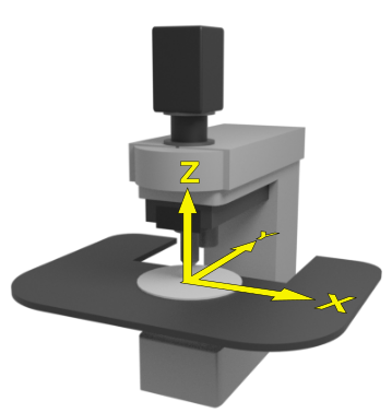
ACQ4 uses a global coordinate system to represent the locations of physical objects and data in the experiment – for example images, cells, pipette tips, and photostimulus patterns. We define the coordinate system as follows:
The origin of the global coordinate system is in the center of the sample / recording chamber, on the top surface of the glass that would hold the sample. (This choice is arbitrary, but we find it helps us visualize and understand the global coordinate system if it always has a consistent origin).
The X axis points toward the right side of the microscope stage, the Y axis points toward the microscope / away from the operator, and the Z axis points up.
The coordinate system has units of unscaled meters. For example, a distance of 10 μm is represented as 10e-6 in this system (in fact, all data in acq4 are represented in unscaled SI units).
1. Camera Scale
This step tells ACQ4 about the physical size of pixels in your camera sensor. For now this is just about the camera sensor itself; later on we will add in the per-objective corrections that let us relate pixels to distances on the sample being imaged.
Look up the pixel size reported by the manufacturer for your camera.
This should be written in to the transform:scale option in the camera config like:
Camera:
    ...
    parentDevice: 'Microscope'
    transform:
        scale: 6.5*um/px, 6.5*um/px
2. Objective Scaling
Here we tell acq4 about the magnification factors of your objective lenses. These factors, combined with the physical size of pixels on your camera sensor, tells us how large one image pixel is relative to the sample that is being imaged.
Make sure all objectives are added to the Microscope device in your device configuration file, with proper scale factors. A 5x objective, for example, should have a scale factor very close to 1.0/5.0. For example:
Microscope:
    driver: 'Microscope'
    parentDevice: 'Stage'
    objectives:
        0:  # first slot
            5x_0.25NA:
                name: '5x 0.25na FLUAR'
                scale: 1.0 / 5.0
        1:  # second slot
            40x:
                name: '40x 0.75na Achroplan'
                scale: 1.0 / 40.0
This value can be adjusted by a small amount to correct for manufacturing tolerance (but most scientific objectives have good accuracy here). Some microscopes may have extra optics to increase or reduce the total magnification. In that case, the extra magnification should be included in the value for each objective.
Verify the scale factor by imaging a micrometer slide and measuring the distance between lines using the ruler ROI tool in the camera module. Check that the scale is reported correctly for all objectives. ACQ4 should automatically keep track of which objective is currently in use and adjust accordingly. If the correct objective is not selected, then a device misconfiguration may be to blame. If your hardware does not support reporting the objective that is currently in use, then it is necessary to manually select the current objective via the Microscope dock in the main Manager window whenever it changes.
3. Camera Orientation
By convention, we say that the global X and Y axes are aligned with the rows and columns of the camera sensor. This is not strictly required (it’s possible to use the camera at any angle); however, we also represent the global X and Y axes as rows and columns of pixels on screen. For image display, it’s appealing to have the camera and screen perfectly aligned.
First we should ensure that the camera image is correctly rotated / mirrored such that the image onscreen matches the orientation of the sample:
The rightward direction onscreen points toward the right side of the rig
The upward direction onscreen points toward the back of the rig, away from the operator
Place an object under the microscope objective that can be used to verify the orientation of the camera. For example, a micrometer slide where the correct orientation is known, or very fine print, or the letter “R” written about 1-2 mm tall on a slip of paper.
Load the camera module and start live video display (click “Acquire Video”); focus on the object.
- The appearance on screen should be in the same orientation as under the microscope:
The rightward and leftward directions for an operator facing the computer screen should be the same as the rightward and leftward directions when facing the microscope. This is the X axis in acq4’s global coordinate system
The upward direction on the screen should be the same as the direction pointing away from the operator, toward the microscope. This is the Y axis in acq4’s global coordinate system.
If the camera view is rotated relative to the physical object, then you can either physically rotate the camera to match, or add a rotation to the camera’s transform->angle configuration option:
Camera:
    ...
    transform:
        scale: 6.5*um/px, 6.5*um/px
        angle: -90                   # rotate camera image 90 deg
If the camera view is reversed (mirrored) relative to the physical object, then you need to multiply one of the x- or y-scale factors by -1 in the camera’s transform->scale configuration:
Camera:
    ...
    transform:
        scale: 6.5*um/px, -6.5*um/px  # invert y axis to flip image vertically
        angle: -90
4. Stage Orientation
The next step is to ensure that acq4 understands how the stage’s x,y,z axes are oriented and scaled relative to the global coordinate system.
- Configure your stage. All stages have different limitations and idiosyncracies that require different handling to use with ACQ4.
Sensapex uMs stage: see SensapexDevice.
Scientifica SliceScope: This can be configured using LinLab (provided by manufacturer), but we recommend configuring via the acq4 config (see Scientifica). so that you know the parameters are being maintained correctly over time. The main factors to work out are:
- What are the axis scale values
Provided by manufacturer, they determine the relationship between motor steps and distance traveled.
Affects the position values returned by the physical device
Can be retrieved from the device if you are not sure what values to use: e.g. man.getDevice(‘SliceScope’).dev.getAxisScale(‘X’)
- Which axis scale values should be negative
Determines which direction on the stage points toward more positive position values
- What direction to move
More importantly, determines which end of the range is zero. This is where auto calibration will take place, so it needs to be
a “safe” location. For a SliceScope z axis (with an inverted microscope), we want Z to be zero at the top of its range because it’s safer to make automatic moves in that direction. For a non-inverted microscope, Z=0 should be at the bottom of its range. Likewise, condenser devices should have their zero point _away_ from the sample holder.
- Objective lift/disp
Set to avoid collisions while switching objectives and to automatically refocus after switching
Note that these values depend on axisScale, so they should be configured afterwards
Note also: ACQ4 itself does not care about these values. It does track the difference in focal plane between the objectives, but
the scientifica controller is responsible for deciding how to move the objectives during switching.
- What direction do you want your rotary controllers to turn
Your choice, but be consistent about it
Note that reversing an axisScale value also reverses the direction of the rotary controller
- How fast do you want the stage to move
- There are a few configurable speeds: “fast”, “slow”, and “user”.
Fast: movements over long distances where vibration is not a factor to consider. Typically 3-5 mm, but this depends on
the device, since some devices will “slip” and become miscalibrated if they are asked to move too quickly. - Slow: Movements over shorter distances, made where vibration is a concern (because of patched cells) - User: Speed to set for rotary controllers
- Check z-axis scale and orientation. We assume that your stage’s Z axis is vertical.
The configuration for your stage device should have a
scale:section that contains x,y,z scale factors to convert from hardware-reported position values to unscaled meters. These values are usually 1e-6 (most devices report their position in micrometers). If you are not certain of this value, choose 1e-6 for now; we’ll correct it later:Stage: driver: 'Sensapex' device: 20 scale: 1.0e-6, 1.0e-6, -1.0e-6 # x, y, z
Note that the scale parameter is at the top level of the Stage config, not inside the transform section. The transform section is used to set the stage’s position in the global coordinate system, whereas the scale section is used to convert from hardware-reported position units to global coordinate units.
Load the Camera module, find the “Depth” plot, and look for the yellow line indicating the Z position of the focal plane (you may need to zoom out using the mouse wheel).
Verify that when focusing the objective lens physically upward, the yellow line also moves upward on-screen.
If not, the
scalesection of the stage’s config should get a sign change on the 3rd numeric value; restart acq4 and verify the Z orientation is correct.
- Set z-axis scale
Open the camera module, start video, and focus on a pipette tip.
In the Camera module’s Microscope dock, click “set surface”. This should display a green line over the yellow line (in the depth plot), and will also make it easier to measure changes in the focus Z position.
Move the pipette tip a known distance in the Z (vertical) direction (e.g. +1 mm).
Adjust focus to match, taking note of the distance traveled – this difference should now be displayed next to the “set surface” button, and will also be visible as the distance between green and yellow lines on the Microscope dock’s depth plot.
If there is any discrepancy between the pipette distance traveled and the focus distance traveled, this should be corrected in the stage’s scale configuration parameter; restart acq4 and verify the stage Z scale is correct. For example, if you moved the pipette 1 mm and acq4 reports that the focus changed by 10 mm, then this indicates that the configuration Z scale factor should be multiplied by 0.1.
If you change the scale factor, remember to restart acq4 and test again.
- Check x/y axis scale and orientation
Focus on something visible (a pipette tip or a piece of dirt will work). Draw an ROI around the object.
Move the stage in the x direction and confirm that the object and ROI move together.
If the object and ROI move in opposite directions on screen, then multiply the stage X scale by -1, restart acq4, and try again.
If the object and ROI move in the same direction on screen but different distances, then correct the scale factor. For example, if the ROI moves twice as far as the object, then divide the X scale factor by 2. Note: the accuracy of this step depends on the accuracy of your micromanipulator. Use large movements to minimize potential errors, or use a micrometer slide if possible.
Repeat in the y direction.
5. Fine Tuning the Stage Orientation
We also find that it’s helpful (but again not strictly required) to have the microscope stage’s X and Y axes well-aligned with the camera. In this step we’ll physically rotate the camera by a small angle until it is well aligned with the stage axes.
Find a small, visible feature in the camera view – dust on the cover glass, a pipette tip, etc. Move the stage until that feature is at the left edge of the view, vertically centered. Add an ROI around the feature.
Move the stage along its X axis until the feature is at the extreme rightmost edge of the view. At this point, the ROI may be a small distance either above or below the feature – their Y position on screen may differ, but their X position should be the same. (If there is a difference in X position, go back to “Check x/y axis scale and orientation”)
Physically rotate the camera a small angle around its Z axis to compensate for half of the observed drift.
Repeat previous steps until the ROI maintains the same Y location as the feature on either side of the view.
6. Set the global coordinate origin
In this step we configure the stage position offsets such that the global coordinate origin lies at the center of the recording chamber, on the glass. This is not strictly required, but often makes our job easier when we need to make sense of those coordinate values.
Aside: there is some complexity behind the calibration described below. We are going to arbitrarily choose the center of the recording chamber, at the top surface of the glass coverslip, to be the origin of the global coordinate system. If we wanted to be able to move the stage+focus such that the center of our camera view is at this origin, then it’s necessary to know: what position does the stage hardware report when the camera view is centered over the origin? Ideally, if we know this value, then we can simply subtract it from the stage’s position in order to move the origin to the center of the recording chamber. Below, we implement this offset using the Stage device’s transform. In practice, however, stage and manipulator devices are not perfectly trustworthy – the positions they report may drift over time. To correct for this, each stage device will have a model-specific mechanism to “re-home” the stage, which ensures that position values are kept stable over time. Depending on the reliability of the stage, this procedure may only need to be performed on occasion when a discrepancy is detected, or perhaps more frequently if the stage is known to drift.
- Re-home the stage device. This is a model-specific procedure that resets the coordinates reported by the device to ensure they are accurate.
For Scientifica SliceScope, this is done by clicking the “Auto set zero offset” button in the device’s dock in the Manager window. Note that this will move the stage to a far extent of its range in order to determine its exact position along each axis. The direction that it travels is determined by the autoZeroDirection parameter in the device’s config (see Scientifica).
For Sensapex uMs, this is done by clicking “Run Zero Calibration” from the device’s dock in the manager window, or (equivalently) running the zero offset calibration command from the touchscreen.
For other devices, consult the manufacturer’s documentation for how to re-home the stage.
Under the high-power objective, center the camera view over the center of the recording chamber and focus on the top surface of the glass coverslip (for in vivo rigs with no coversliip, pick any suitable focal plane to be the Z origin). If this is a water immersion objective, it is important to be dipped in water (ideally saline) at this point.
In the manager window, under the Microscope dock, make sure the x,y,z values for the high power objective are all set to 0.
In the camera window, point your mouse cursor close to the center of the view and note the x,y coordinates displayed in the bottom right corner of the camera module window. We would like these to read (0, 0) so that the origin of the global coordinate system is at the center of the recording chamber. The z position is displayed in the Depth dock on the right-hand side of the camera window, and we would like the 0 here to mean “on the glass”. Note: If you have a multi-well setup, you might choose to place the origin in the center of a specific well, or in the center of all wells, etc.
To move the origin, we will subtract the currently displayed x,y,z position values from the
transform -> possetting in the stage’s device configuration. (if no setting exists here yet, the values are assumed to be 0):Stage: driver: 'Sensapex' device: 20 scale: 1.0e-6, 1.0e-6, -1.0e-6 transform: pos: -3.45*mm, -12.27*mm, 8.552*mm
After correcting these values, restart acq4 and confirm that the global origin is roughly where you expect it to be.
7. Objective offset calibration
In this step we tell acq4 how far apart the focal planes and objective centers are for your objectives. Note that some objective changers will attempt to automatically adjust the focal position when switching to compensate for parfocality; this calibration step does _not_ affect that behavior, and also is not affected by that behavior.
Focus on a pipette tip under the highest power objective. If you are using an immersion objective, then the pipette tip and objective should be dipped in saline. Note: we assume here that you have a standard 2-objective ephys rig, but these instructions should apply easily to more objectives.
In the manager window, under the Microscope dock, make sure the x,y,z values for the high power objective are all set to 0. These values will _stay_ 0 because by convention we calibrate the position offsets of each objective relative to the highest power objective.
Draw a small ROI around the tip of the pipette and click the “set surface” button. This gives us a reference point (green line in the depth plot) for measuring the offset between two objectives.
Switch to the low power objective, remove the saline from around the pipette (assuming this is an air objective), and focus on the pipette (but don’t move the stage x/y axes) Note: the reason we do this calibration in saline for the high power objective and in air for the low power objective is that these are the most common conditions under which we will want to “transfer” pipette positions from one objective to another – in some setups we do a coarse pipette calibration in air under the low-power objective, then do a refined calibration under high power dipped in saline.
In the manager window, under the Microscope dock, adjust the x,y values for the low-power objective until the pipette tip is matched to the ROI again. Likewise, adjust the z value until the yellow focus line is matched to the green “surface” line.
Copy the x,y,z values you have chosen in to the objective offset position in the microscope configuration. Do this for all objectives (including the high-power objective with values set to 0):
Microscope:
    driver: 'Microscope'
    parentDevice: 'Stage'
    objectives:
        0:  # first slot
            5x_0.25NA:
                name: '5x 0.25na FLUAR'
                scale: 1.0 / 5.0
                offset: -43*um, 9*um
        1:  # second slot
            40x:
                name: '40x 0.75na Achroplan'
                scale: 1.0 / 40.0
Verify after restarting acq4 that the offsets are working correctly by repeating steps 1-4.
8. Initial manipulator calibration
This procedure should be performed any time a manipulator is physically reconfigured (like if the orientation of the manipulator or headstage is adjusted), or whenever it appears that the manipulator calibrations are no longer correct. Before starting this procedure, it is a good idea to make sure your manipulator is securely seated in a good position such that:
Pipette tips can reach a large enough area in the center of the recording chamber as well as any needed cleaning wells. To maximize available reach, it may help to orient the manipulator such that a cleaning well is at one corner of the manipulato’s x/y range, and the center of the recording chamber is at the opposite x/y range
The headstage should be unlikely to collide with the microscope
Collisions with nearby manipulators are not possible
If your manipulator position meets these requirements,
- Run calibrations recommended by the hardware manufacturer, if needed.
- For Sensapex uMp:
Move manipulator to a safe position and remove the pipette+holder. NOTE: The manipulator will move over its full range of motion, so it is important that no collisions are possible during this calibration.
Run the position calibration from the sensapex touchpad (tap the manipulator icon [4th from left along the screen bottom], then expand the “Setup” group, then “Calibrate positions”).
- For Scientifica manipulators:
Scientifica manipulators track their position relative to a hardware zero point, which is retained across power cycles. The zero point only needs to be re-established if the motor has slipped or was rotated while the device was powered off.
- There are two ways to set the zero position from the device’s dock in the Manager window:
“Zero position”: Sets the current position as the new zero on all axes. Use this when the manipulator has already been moved to its mechanical limit manually.
“Auto-set zero position”: Drives each axis to its mechanical limit switch and sets that as the zero position. This is the recommended approach. NOTE: The manipulator will move to the limit of its range on each axis. Ensure the device is not obstructed before using this feature. A confirmation dialog will appear before any movement begins.
Per-axis variants (“Auto-set X/Y/Z zero”) are also available if only specific axes need to be re-zeroed.
Calibrate manipulator axis orientation. This step tells acq4 about the direction that each manipulator axis points relative to the global coordinate system:
Put a new pipette and the high-power objective in solution in the recording chamber. Watch via the camera for a few minutes to verify that the pipette is not drifting. In case of drift, reduce any sources of temperature change – especially block all air flow around the rig and microscope.
In manager window, find the dock for the manipulator device to be calibrated (e.g. “Sensapex1”) and click “calibrate”. This opens a new window that manages the collection of calibration data points, which will be used to determine the manipulator axis directions.
In the calibration window, remove all calibration points (if any) by selecting and clicking “remove”.
Move the stage to the center of the recording chamber and focus near the plane where you will normally be patching (if you’re patching cultured cells, ~10µm above the glass is ok).
In 40x, move the pipette to the left edge of the view, vertical center. The tip should be in sharp focus.
Click “add point” in the calibration window, then click on the pipette tip. This should be done carefully – zoom in and pick a specific feature of the pipette tip that you will be able to click on repeatedly. It may help to take a screenshot here as a reference to ensure that you can repeatedly achieve the same focus and point position.
Move the pipette ~50µm to the right using _only_ the manipulator X axis (do not move the manipulator y/z axes). Re-focus on the tip (using the microscope focus) and add another point. Continue adding points until the pipette tip reaches the right side of the view. During this entire process, the manipulator Y and Z axes must remain unchanged. To calibrate the orientation of each axis, you need a minimum of three calibration points per axis. However, it is recommended to collect several points per axis for better accuracy.
Now repeat the process for the Y and Z axes – start from the top edge / horizontal center and work your way downward in Y (leaving X and Z unchanged), then start in the center of the screen and work your way upward in Z (cover at least ~100 µm in Z range).
Click “save calibration”.
- Test axis orientation calibration:
Under the multipatch module, enable the pipette by clicking on its numbered button (and disable all other pipettes)
Click “calibrate”, then click on the pipette tip in the camera module
Focus on a random x/y/z location, click “set target” in the multipatch module, then click any location in the camera module. A yellow target symbol should appear where you clicked.
Click “to target” and wait for the pipette tip to move. If the calibration was successful, the pipette tip should come very close to the target. Otherwise, it’s likely a mistake was made during the calibration procedure.
Check the Z error by using the camera module’s depth chart (compare the yellow focus line to the blue pipette triangle; you may need to zoom in using the mouse wheel).
Within the field of view where calibration was performed, errors should be very small (on the order of 1 µm). As you move farther from the original calibration site (the center of the recording chamber), you should expect some x/y error to accumulate.
9. Set home and cleaning positions for each manipulator
- Set home position
Move manipulator to the center of its y range, almost to the top of its z range, and almost to the end of its x range away from the recording chamber.
In the manager window, under the dock for the manipulator device (e.g. “Sensapex1”), click “Set Home”
- Set clean / rinse positions
Move pipette tip into the cleaning well, at the desired depth for cleaning. Note: during automated pipette cleaning, the manipulator is programmed to move a certain distance above the cleaning position before entering the cleaning well. The default distance is 5 mm, but this can be set in the configuration for patch pipette states under “clean -> approachHeight”. If the manipulator cannot move this distance above the selected cleaning position, then an error will occur. Now is a good time to make sure there is enough room to satisfy this constraint.
In the manager window under the dock for the patch pipette device (e.g. “PatchPipette1”), click “Set Clean Pos”.
Repeat for rinse position if needed.
10. Configure pipette approach angle
ACQ4 needs to know the orientation of your patch pipette in order to do motion planning for automated actions. For example, when driving the pipette in and out of tissue we usually want it to move only along its axis; never laterally through the tissue.
Although some of this information may be related to your manipulator orientation, this is not always a reliable assumption so it is necessary to tell ACQ4 about your pipette orientation.
Configure pitch and yaw in the device configuration
Add the pitch and yaw parameters to your Pipette device configuration:
pitch (float or ‘auto’, required): The angle of the pipette (in degrees) relative to the horizontal plane. Positive values point downward.
yaw (float or ‘auto’, required): The angle of the pipette (in degrees) relative to the global +X axis (points to the operator’s right when facing the microscope). Positive values are clockwise from global +X.
Example configuration:
PatchPipette1:
    driver: 'Pipette'
    parentDevice: 'Manipulator1'
    pitch: 15.0     # pipette points 15° below horizontal
    yaw: 45.0       # pipette points 45° clockwise from global +X axis
Alternative: Use automatic configuration
If your pipette is aligned with one of your manipulator’s axes, you can use
'auto'for pitch and/or yaw:PatchPipette1: driver: 'Pipette' parentDevice: 'Manipulator1' pitch: 'auto' yaw: 'auto' parentAutoAxis: '+x' # pipette aligned with +X axis of manipulator
Valid values for parentAutoAxis are:
'+x','-x','+y','-y','+z','-z'.Test the configuration
Focus to about 300 μm above the glass coverslip (if stage/objective configuration was done correctly, the yellow focus line in the camera module’s depth chart should be at +300 μm) and click “set surface” in the camera module. This tells ACQ4 where the surface of the (imaginary) sample is located, which will be used later to determine how to correctly move the pipette.
Focus 50 μm below the surface line and click “set target” in the multipatch module, then click in the camera view. This sets the target position for the pipette, and a yellow target symbol should appear at the clicked position.
Click “approach” in the multipatch module. The pipette should move to a position that is above the surface line, aligned with the target position. (Depending on your configuration, the pipette may also begin advancing towards the target position. If so, press esc to stop the pipette.)
Manually drive the pipette along its approach axis until it reaches the target position. Scientifica and Sensapex manipulators both provide “approach” or “diagonal” modes of operation that drive the pipette along its axis.
Verify that the pipette reaches the target (in x, y, and z) using only axial motion. If all parts of the system are calibrated correctly, the pipette should reach its target within several micrometers (the actual amount of error depends on the conbined quality of the calibration and manipulator hardware).